Choosing the best Lightning Protection Materials requires more than comparing prices or metal thickness. The system must carry enormous electrical energy safely through air terminals, conductors, bonds, grounding electrodes, and surge protective devices. Copper offers excellent conductivity and durability. Aluminum can reduce weight and cost, but it requires careful attention near copper and masonry. Stainless steel may perform well in corrosive environments, although its higher price deserves realistic evaluation.
Dr. Martin A. Uman, a leading lightning researcher, described lightning simply: “Lightning is a giant electrical spark.” That sentence explains the design challenge. Materials must manage sudden energy, not merely remain outdoors. Selection should consider conductivity, tensile strength, corrosion resistance, connection quality, installation conditions, and expected maintenance. UL 96A, NFPA 780, and IEC 62305 provide useful technical references, but competent professionals should verify the latest applicable requirements.
A practical inspection reveals important details. Look for clean joints, protected transitions, secure fasteners, and separation from incompatible metals. Coastal salt, industrial fumes, rooftop moisture, and buried soil chemistry can change performance over time. A material that performs well in a dry warehouse may fail earlier beside a wet seaside roof. No selection method is flawless. Cost-focused decisions can overlook corrosion, replacement access, or poor bonding. That is where reflection matters. The best choice balances engineering evidence, site experience, verified product quality, and long-term reliability. Choose deliberately. Safety depends on the complete system, not one impressive component.
Choosing the Best Lightning Protection Materials Starts with Risk
IEC 62305 divides lightning protection into Levels I–IV. Level I addresses the most severe exposure. Level IV represents the lowest design intensity. The correct level comes from a formal risk assessment, not material preference.
IEC 62305-2 evaluates lightning density, building dimensions, occupancy, services, and possible losses. It also considers fire, public safety, and interruptions. Vaisala’s 2023 Annual Lightning Report recorded more than 8 billion global lightning events. That figure shows why local exposure data matters. A coastal warehouse and an inland office should not share one automatic specification.
For LPL I or II, engineers commonly require robust air-termination conductors, reliable bonding, and coordinated surge protective devices. Materials must withstand thermal, mechanical, and corrosion stresses. Copper, aluminum, and suitable steel can perform well when selected for the environment. Compatibility matters. Poor metal connections can accelerate corrosion and weaken continuity. That detail is often missed.
Tips: Start with the site’s lightning density and loss profile. Then calculate the IEC 62305 risk. Match conductor size, separation distance, earth electrodes, and surge protection to the assigned level. Inspect joints after installation, especially near rooftop equipment. Document test results. Do not trust appearance alone.
In practice, the design may need adjustment. Soil resistivity can change across one site. Construction details may also invalidate an early drawing. Experienced engineers should review assumptions before procurement, because the cheapest material can become the most expensive failure.
Assess site risk using IEC 62305 Lightning Protection Levels I–IV. The protection level determines the lightning current range and the rolling-sphere radius used when designing air-termination systems.
IEC 62305-1 assigns progressively lower lightning-current thresholds from LPL I to LPL IV. The rolling-sphere radius is 20 m, 30 m, 45 m, and 60 m respectively. Use the selected LPL, exposure conditions, corrosion environment, and mechanical requirements to specify compatible conductors, air terminals, bonding components, and earth electrodes.
Choosing lightning protection materials begins with the design current, not the catalogue label. IEC 62305-1 identifies 200 kA as the maximum lightning current used for Lightning Protection Level I. That figure demands conductors with predictable impulse performance, secure bonding, and low-impedance routing.
Conductivity matters. The International Annealed Copper Standard assigns annealed copper a reference value of 100% IACS at 20°C. ASTM B193 defines the corresponding resistivity as approximately 0.017241 ohm·mm²/m. Aluminum is commonly rated near 61% IACS, so a comparable resistance requires a larger cross-sectional area. However, conductivity alone does not prove suitability. IEC 62305-3 also addresses conductor dimensions, separation distance, joints, and mechanical installation. A sharp bend can increase inductive voltage during a fast surge.
Do not overlook connections. A 200 kA impulse can create severe electromagnetic forces at poorly secured joints. Use tested clamps, short paths, smooth bends, and corrosion-compatible interfaces. Copper often offers higher conductivity in a smaller conductor, while aluminum can reduce weight and material cost. The choice depends on exposure, installation environment, and compatibility with bonded metalwork. A common mistake is selecting the smallest permitted conductor and assuming the standard guarantees every installation. It does not. Project calculations should verify thermal stress, voltage rise, and mechanical restraint using the actual routing. That extra review may seem excessive, but lightning rarely follows convenient assumptions.
Choosing lightning protection material starts with conductivity, but the site often decides the outcome. Annealed copper measures 100% IACS conductivity, according to International Annealed Copper Standard data. Aluminum reaches approximately 61% IACS, while common structural steel often falls near 10–15%. These figures come from published resistivity tables referenced by IEC 62305-3. Copper therefore carries lightning current with less resistance and usually permits smaller conductors. Aluminum is lighter, which helps when installing long rooftop runs. Steel remains mechanically strong, but its lower conductivity demands careful sizing and bonding.
Corrosion changes the comparison. Copper generally performs well in outdoor air, although polluted or marine environments can stain and accelerate surface attack. Aluminum forms a protective oxide layer, yet alkaline concrete, trapped moisture, and contact with copper can create galvanic corrosion. Steel needs reliable coating protection, especially at cut edges, clamps, and buried sections. The NACE IMPACT Study estimated global corrosion costs at about 2.5 trillion dollars in 2013, equal to roughly 3.4% of global GDP. That figure is not a material ranking. It is a warning about neglected maintenance.
In field installations, dissimilar-metal joints deserve extra attention. Use compatible connectors, keep water from collecting, and inspect bonds after severe weather. Small details matter. Copper may be the safest electrical choice, but not always the most practical one. Aluminum can reduce structural loads, while steel may suit exposed mechanical routes. This is where neat comparisons fail: conductivity, coating damage, soil chemistry, and workmanship interact.
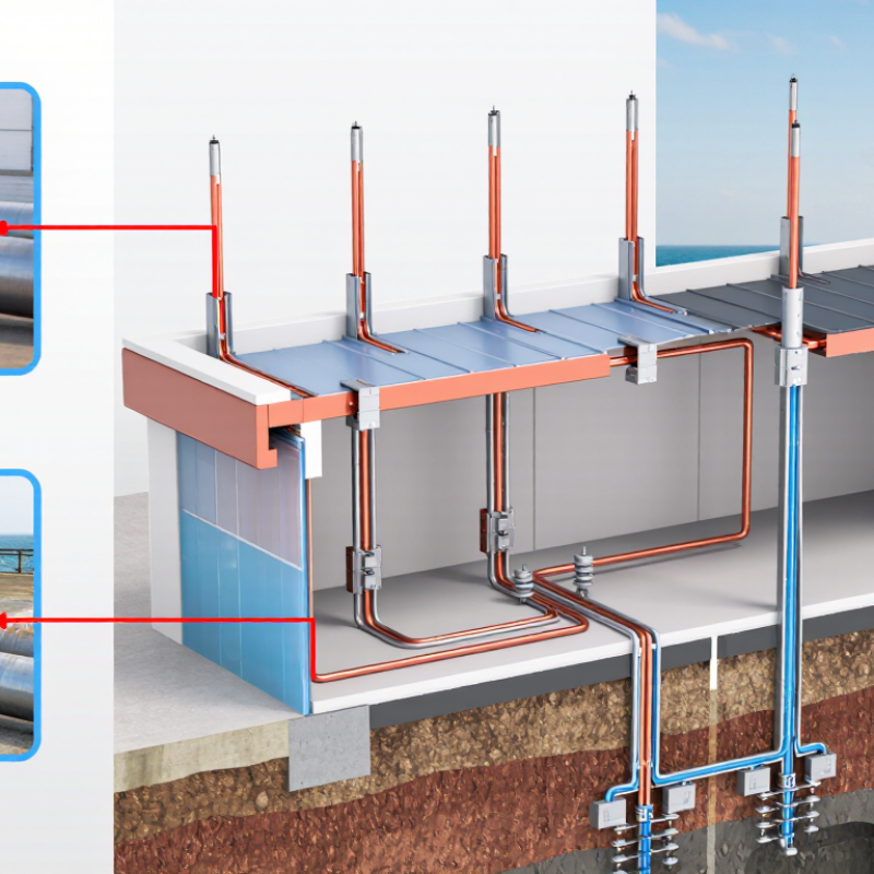
Choosing lightning protection materials starts with the installation environment, not the product catalog. NFPA 780 addresses air-terminal placement, conductor routing, grounding, and bonding. UL 96A adds installation requirements for lightning protection systems. Together, these standards help designers match terminals, down conductors, clamps, and bonds as one system. A copper terminal beside aluminum roofing needs careful separation or compatible transition hardware. Otherwise, corrosion can quietly weaken the path.
Scale matters. NOAA’s National Severe Storms Laboratory reports roughly 25 million lightning flashes across the United States each year. NFPA’s Lightning Fires and Lightning Safety report estimated about 22,600 U.S. lightning-caused fires annually during 2007–2011. These figures are older, but they remain useful risk indicators. They also expose a common mistake: treating an air terminal as standalone protection. The current must travel somewhere.
During a field review, verify terminal spacing, conductor bends, roof penetrations, and bonds to major metal bodies. Follow NFPA 780’s bonding provisions, then confirm that selected components satisfy applicable UL 96A requirements. Check corrosion resistance, mechanical strength, and electrical continuity after installation. Documentation matters. Photograph hidden bonds before closure. A practical weakness deserves attention: drawings often show ideal routes, while roofs contain ducts, parapets, and later additions. Recheck the completed system, not merely the approved design.
| System Element | Recommended Material Selection | Common Minimum or Selection Data | NFPA 780 Checkpoint | UL 96A Installation Checkpoint | Important Field Consideration |
|---|---|---|---|---|---|
| Air terminal (solid copper) | Solid copper with suitable mechanical strength and corrosion resistance. | Minimum diameter: 3/8 in (9.5 mm) for a commonly specified solid round copper air terminal. | Use an air terminal with a height and spacing arrangement that protects the exposed roof area and connected objects. | Use a component evaluated for lightning protection service and install it according to its listing and installation requirements. | Suitable for many copper-based systems. Check contact compatibility when connecting to aluminum components. |
| Air terminal (solid aluminum) | Solid aluminum that is suitable for exterior exposure and compatible with the rest of the system. | Minimum diameter: 1/2 in (12.7 mm) for a commonly specified solid round aluminum air terminal. | Aluminum should not be installed where it may be exposed to damaging corrosive conditions or unsuitable contact metals. | Confirm that the air terminal and its base or connector are listed or accepted for the intended lightning protection installation. | Do not make a direct copper-to-aluminum connection without a connector designed for that material combination. |
| Air-terminal projection | Copper or aluminum air terminal selected according to the roof geometry and protection method. | At least 10 in (254 mm) above the object or roof area being protected is a commonly referenced minimum projection. | Place terminals to provide the required zone of protection; terminal height alone does not replace correct spacing and layout. | Follow the listed system design and installation instructions for terminal placement, bases, and attachment hardware. | Account for parapets, rooftop equipment, signs, vents, photovoltaic equipment, and other exposed projections. |
| Main lightning conductor | Use copper or aluminum conductor matched to the selected air terminals and the environmental conditions. | Common minimum cross-sectional references: copper 29 mm²; aluminum 50 mm². | Conductors must be routed as directly as practicable, with secure supports and no unnecessary bends or loops. | Use conductor types, fittings, and attachment methods recognized for lightning protection installations. | Maintain continuity through joints and protect conductors from physical damage, sharp edges, and incompatible metals. |
| Down conductors | Copper or aluminum conductors with the same material-compatibility controls used for the roof conductors. | Provide at least two down-conductor paths for a typical building perimeter system, distributed as evenly as practical. | Use multiple paths to reduce impedance and divide lightning current; route conductors away from combustible or easily damaged materials where required. | Install listed or accepted connectors, clips, fasteners, and test points according to the system installation requirements. | Coordinate down-conductor routes with doors, windows, utilities, structural joints, and accessible public areas. |
| Bonding conductor | Use the same or a compatible conductor material as the lightning protection system; use approved bimetallic fittings for dissimilar metals. | Size the bond according to the applicable bonding provisions, connected metalwork, conductor length, and required fault or lightning-current path. | Bond metal bodies and grounded systems when required to reduce side-flash risk and maintain equipotential conditions. | Use connectors and bonding fittings suitable for the conductor material, environment, and intended lightning protection application. | Do not rely on paint, corrosion, loose hardware, or incidental metal-to-metal contact to provide a reliable bond. |
| Structural steel bond | Mechanical or exothermic connection selected for the steel type, conductor material, and installation environment. | Provide a low-impedance connection with adequate mechanical strength and long-term corrosion resistance. | Bond structural metal when it is used as part of the lightning protection system or when required to reduce dangerous potential differences. | Use a connection method accepted for lightning protection work and follow the connector manufacturer’s preparation and torque requirements. | Remove coatings only as required, protect the finished connection, and verify continuity after installation. |
| Metal roof or metal equipment bond | Use a compatible conductor and listed or accepted roof/equipment bonding fitting. | Bond exposed metal items that may experience a side flash or become energized during a lightning event. | Evaluate rooftop metalwork, mechanical equipment, railings, tanks, antennas, and other conductive objects within the protected area. | Install fittings according to their listed use, substrate requirements, attachment method, and environmental limitations. | Verify that roofing membranes, thermal breaks, coatings, and isolation pads do not interrupt the intended bonding path. |
| Grounding electrode connection | Copper or other permitted conductor material selected for direct-burial, soil, and corrosion conditions. | Use the applicable conductor size and electrode arrangement required by the adopted lightning protection and electrical standards. | Connect down conductors to a suitable grounding electrode system and coordinate the lightning grounding system with the building grounding and bonding system. | Use compatible listed or accepted grounding connectors and protect accessible connections from damage and corrosion. | Aluminum components require special attention near earth and concrete because of corrosion and chemical compatibility concerns. |
| Dissimilar-metal connection | Compatibility control Use bimetallic connectors, transition plates, or other fittings specifically designed for the two metals. | Do not place bare copper directly against aluminum where moisture can create galvanic corrosion. | Protect connections from galvanic action, moisture accumulation, and corrosive environments. | Confirm that the connector is suitable for the exact conductor materials, surface type, and exposure conditions. | Apply approved corrosion protection after making the connection; do not substitute ordinary electrical lugs unless accepted for the application. |
| Fasteners and supports | Corrosion-resistant hardware compatible with the conductor, roof assembly, and local environment. | Support conductors securely while avoiding damage to membranes, flashing, insulation, and waterproofing systems. | Maintain conductor continuity and protect the system against mechanical displacement, wind, vibration, and thermal movement. | Use hardware and attachment methods covered by the component’s intended installation use. | Use roof-compatible bases and penetrations; seal penetrations in accordance with the roofing system requirements. |
| Inspection and continuity verification | All air terminals, conductors, bonds, joints, and grounding connections should remain accessible for inspection where practical. | Check mechanical tightness, visible corrosion, conductor routing, bonding continuity, and damage after installation. | Inspect the completed system and verify that required components are installed in accordance with the design and standard. | Confirm installation details, component markings, and field modifications remain consistent with the applicable requirements. | Reinspect after roof replacement, major equipment changes, structural alterations, or a known lightning strike. |
Before purchasing, verify how the materials were tested. Products should match recognized requirements, such as IEC 62561 or NFPA 780. Ask for test reports, not only a certificate number. The report should identify the exact product, test method, laboratory, and approval date. An ISO/IEC 17025-accredited laboratory adds useful confidence. Certificates are not enough.
The World Meteorological Organization’s 2021 Atlas recorded more than 2,000 lightning deaths worldwide between 1970 and 2019. The U.S. National Weather Service also reports about 20 lightning fatalities annually in the United States. These figures justify careful selection, especially for exposed roofs, towers, and public buildings. Check conductor cross-sections, corrosion resistance, connector strength, and compatibility between metals. A shiny clamp can still fail under heat, vibration, or poor bonding.
Installation quality matters as much as material quality. IEC 62305 emphasizes coordinated air terminals, down conductors, equipotential bonding, and earthing. Request installation drawings, continuity measurements, connection torque records, and dated inspection photographs. Do not accept a single earth-resistance reading as complete proof. Soil moisture can change the result. Inspectors should also look for loose clamps, sharp conductor bends, hidden corrosion, and damaged roof membranes. Document everything. A missed connection may remain invisible until a storm exposes it.

Since 1984, Thermostop has been a reputable manufacturer of Industrial Sectional Doors, Cold Storage Doors and Specialty Doors such as Impactable Breakaway doors, Acoustic Doors and Ballistic Doors.
Contact